Front Panel Illumination
The AVB Tool front panel illumination reveals the current device state at a glance. It combines:
-
full color LEDs at each input
-
a standby indicator with integrated status warning
-
a display with level meters and status feedback
Each of these three elements can be individually switched off (dark mode).
Dark Mode
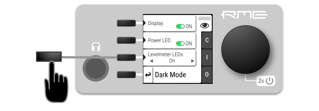
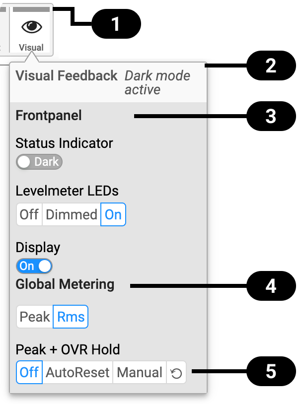
Each of the three front panel illumination sections can be switched off if they are not required.
-
Open the visual feedback tab in the STATE section.
-
Change any of the following:
-
Display to
 Off to turn off the display.
 -
Status indicator to
Off to turn off the standby/status indicator  .
. -
LED Meters to Off or Dimmed to turn off or dim channel LEDs.
-
|
When any item is turned off, a notification (orange) is shown in the STATE section. |

-
Open the same menu and set the corresponding switches to
 to On.
| To turn the front panel lighting on temporarily, just rotate or push the encoder. The panel will turn back off after five seconds. |
-
Connect to the device remotely (see: Remote Control Overview).

Status Indicator

State of Visual Feedback

Front Panel Dark Mode

Global Metering Options

Peak/Over Hold Reset
-
Use the corresponding toggle switches on the web remote to switch off device lighting.
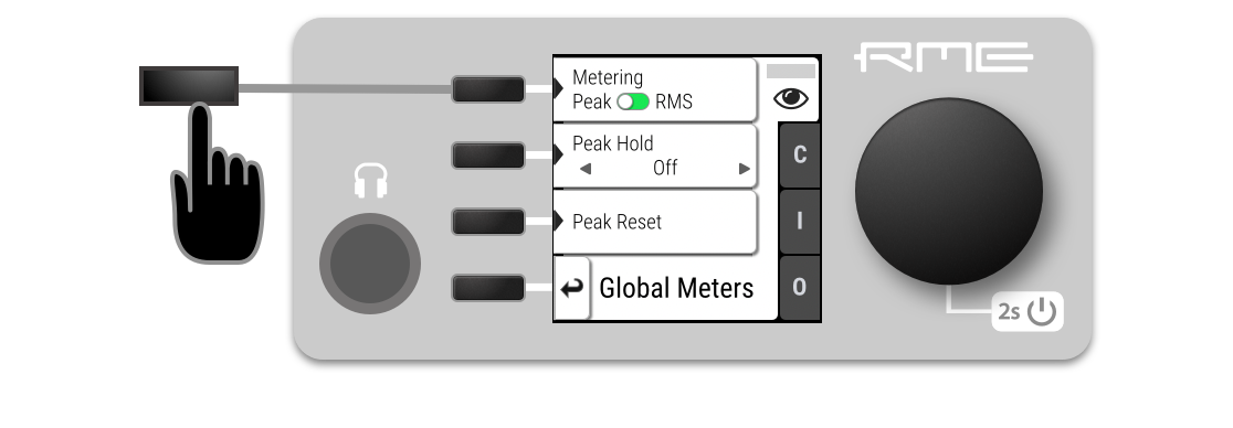
Changing the Meters to Peak or RMS Mode
Depending on the application, instantaneous peak level metering or a slower, averaged RMS metering may be preferred.
-
Open the visual feedback tab in the STATE section.
-
Open "Global Meters" using the corresponding button.
-
Press the first button to toggle between Peak and RMS metering.
-
Connect to the device remotely (see: Remote Control Overview).
-
Locate the visual feedback tab in the STATE section.
-
Push the Peak or RMS button in the global metering settings.
| This is a global setting which affects both the front panel level meters and the remote control interface. |
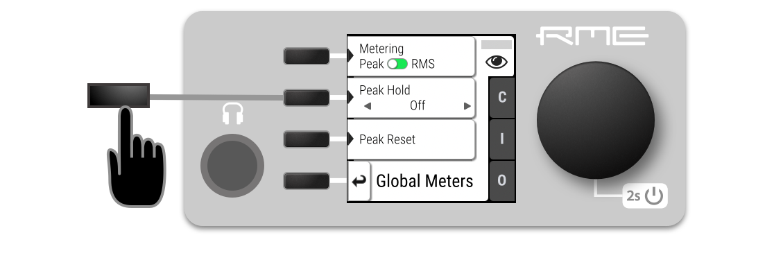
Persistent Clipping Notifications and Peak Hold
The maximum level of signals can be saved and shown on the front panel and web remote. Clipping is detected when three consecutive samples reach digital full scale (0 dBFS). The duration of how long the maximum level or clipping is shown can be manually changed to either five seconds or until they are manually reset.
| This is a global setting which affects both the remote control and the device. |
|
On the device, an over notification is signaled as a fast flashing (red) of the channel LED. |

-
Open the visual feedback tab in the STATE section
-
Change Peak Hold to either:
-
5s to notify for five seconds
-
On to notify until manually reset
-
Off to deactivate over notifications.
-
-
Open either the INFO menu from the standby screen or the visual feedback - Global Meters tab in the STATE section.
-
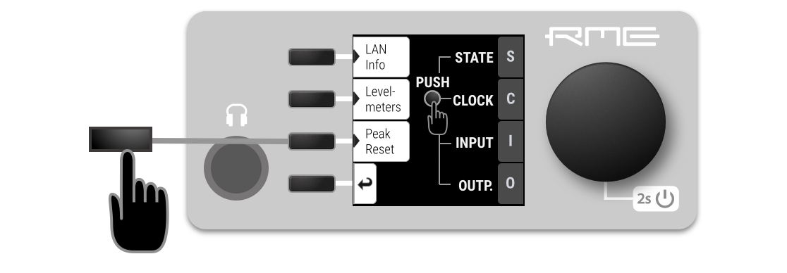
Push the Peak Reset button.
| From the standby screen, press the third button twice to reset the over notifications on the device. |
![]()
The remote shows an over notification above the level meter, both in miniature port level meters and the larger level meters when a port is open.
-
Locate the Visual Settings Tab.
-
Change Peak + OVR Hold to either
-
5s to notify for five seconds
-
On to notify until manually reset
-
Off to deactivate over notifications
-
-
Within the Visual Settings Tab, use the reset button:
 .
.
Metering of Digital Signals
The incoming and outgoing digital signals can be visually inspected to ensure that signals are properly connected and routed. Level meters are included for each port in the corresponding input and output sections, but they can also be inspected quickly from the main window without using the main menu:
-
Open the info section (third button) i from the main screen.
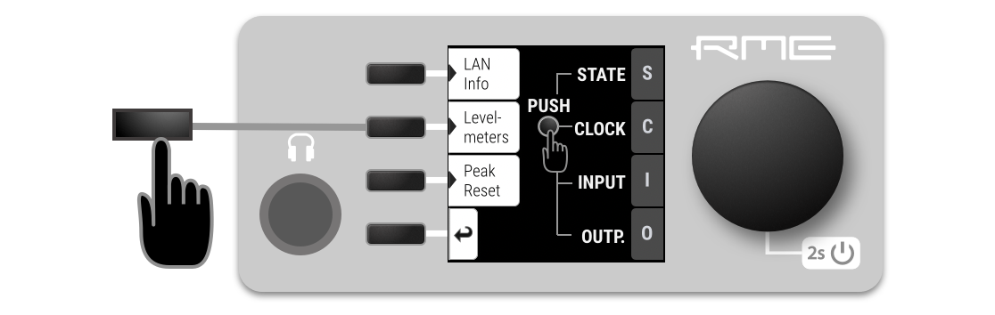
-
Open the tab "Levelmeters".
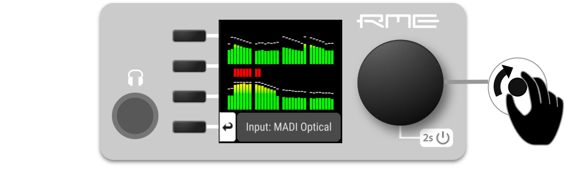
-
Turn the encoder knob to step through the input and output signals.
On the web remote, each input and output port has integrated level meters.
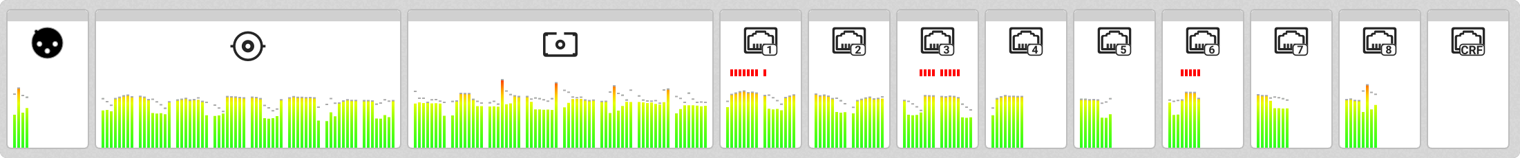
When opening the ports, larger levelmeters are shown with precise levels in dBFS RMS or peak.