AVB Input Streams
The AVB streams received by the M-32 AD Pro are referred to as "input streams". For these streams, the device acts as an AVB Listener.
To establish a connection between a talker and a listener, an ATDECC Controller is required. The M-32 AD Pro does not include an ATDECC Controller.
AVB input streams are monitored as follows:
| Description | Indicator | Possible solution |
|---|---|---|
Disabled |
grey |
Create connection with ATDECC controller |
Streaming/Receiving |
green |
|
No Data |
red |
Verify proper talker configuration |
SR Mismatch |
red |
Verify that the sample rates of talker and listener are identical |
Waiting |
yellow … |
Waiting for talker to be ready |
Talker Fail |
red |
Verify proper talker configuration |
No Bandwidth |
red |
Use faster network speed (1 GBit/s instead of 100 MBit/s) |
Domain Boundary |
red |
Reconnect all devices and reboot switch, ensure only AVB switches are used |
Internal Error |
red |
Reboot device |
Change AVB Input Stream Size
Each of the eight AVB streams can have a size of 1-8, 12 or 16 channels in AM824 and AAF stream formats.
-
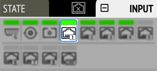
Open the AVB tab in the INPUT section.
-
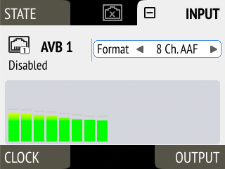
Move the cursor to highlight the corresponding AVB stream size and press the encoder.
-
Rotate the encoder to configure a new stream size and format, then confirm by pressing the encoder again.
-
Connect the device by USB or network cable and open the Remote Control Overview.
-
Open an AVB port in the routing area and use the up and down arrows
 to adjust the stream size.
 -
Use the stream format dropdown
 to select the format to be used.
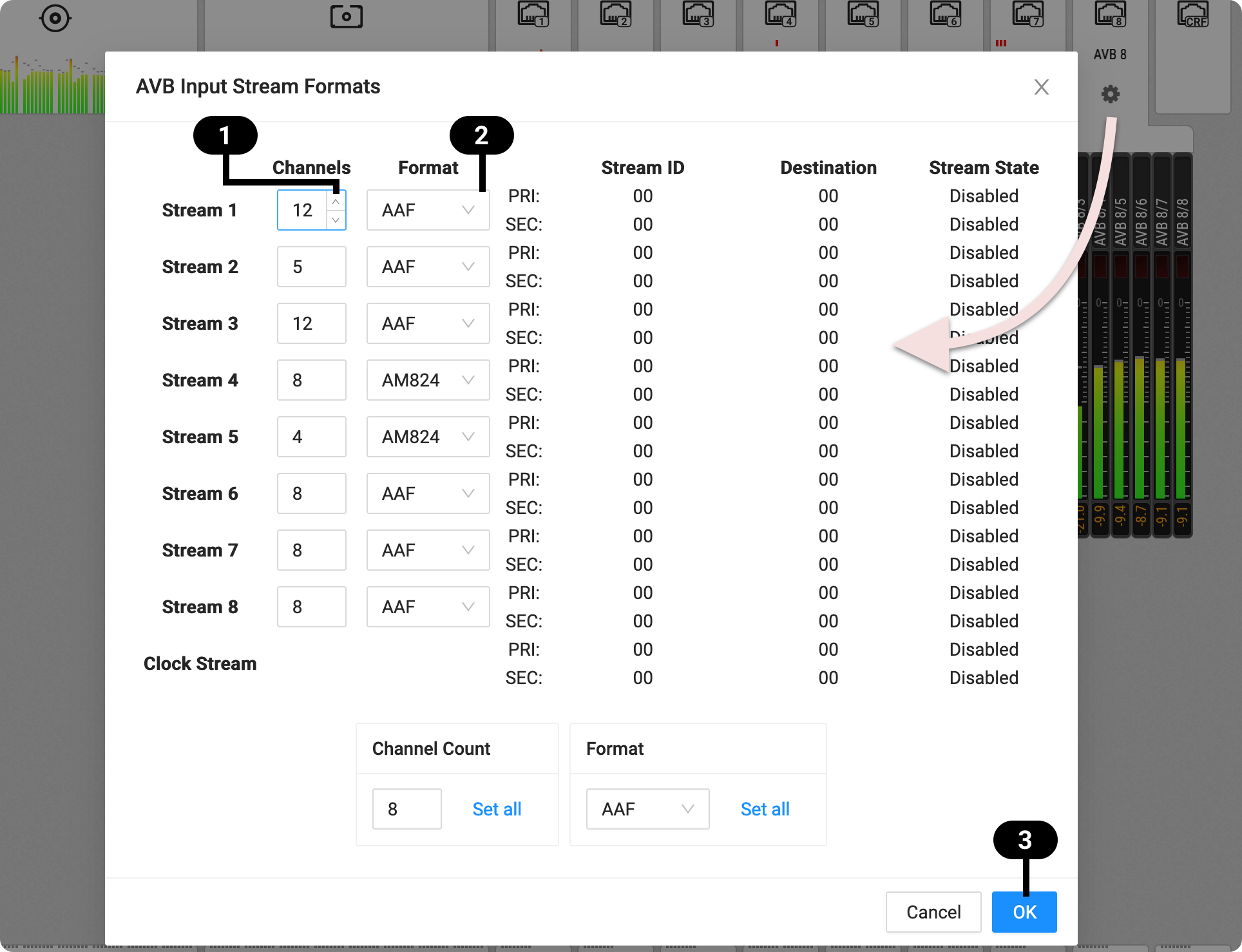
-
Click OK
 .
.
| Changing a stream size briefly interrupts all incoming AVB streams. |
| Incoming streams can contain less than the specified amount of channels. |