Analog Outputs
The line level outputs of the M-1610 Pro operate at +13 dBu, +19 dBu, or +24 dBu. Each individual channel has its own line level setting, which can be adjusted remotely. Additionally, channels can be muted globally or individually.
In its default state, no routing exists between the digital inputs and the analog outputs. Each group of four consecutive outputs can receive its signal from any digital input that is connected and synchronized.
At all sample rates, the converters operate with short delay IIR filters. At single speed, a short delay 'sharp' filter is used to ensure linear frequency response. At double and quad speed, a short delay 'slow' filter is used to optimize the transient response of the M-1610 Pro while maintaining linear frequency response in the audible range. The filters can be changed in the State menu.
Adjusting the Output Line Level
-
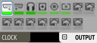
Open the Analog Output Configuration tab in the OUTPUT section.
-
Initially, the cursor will highlight all output channels. To accept this, rotate the encoder to move the cursor to the current reference level.
-
Alternatively, pressing the encoder on the channel strip allows the selection of an individual channel.
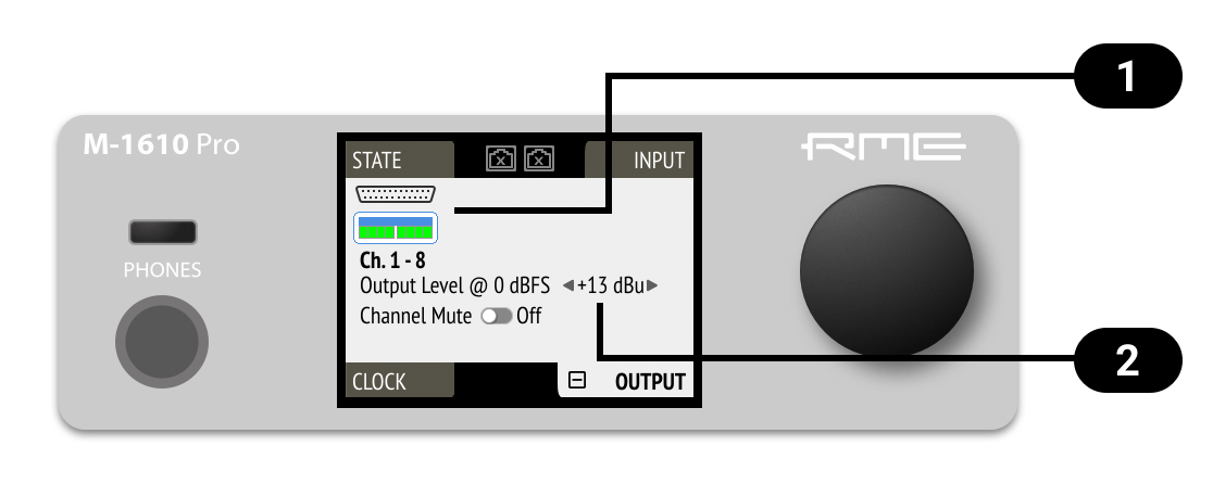

Cursor (current channel)

Output Reference Level
-
Move the cursor to the current line level and push it.
-
Rotate the encoder to change the setting and confirm by pushing the encoder again.
-
Select an analog output channel by clicking the corresponding channel strip. The channel strip turns blue.
-
(optional) Click and drag left or right to select multiple channels.
-
Press one of the buttons for +13 dBu, +19 dBu or +24 dBu below the selection. The selected value is shown within the level meter.
Mute Analog Outputs
-
Open the Analog Output Configuration tab in the OUTPUT section
-
Initially, the cursor will highlight all output channels. Press the encoder, then rotate the encoder to move the cursor to the channel that should be muted.

Cursor (current channel)
Channel Mute
-
Move the cursor to Mute Toggle and push it.
-
Select an analog output channel by clicking the corresponding channel strip. The channel strip turns blue.
-
(optional) Click and drag left or right to select multiple channels.
-
Toggle the Mute switch. The status is reflected with a red M in the corresponding level meters.
Phones Out
The front TRS connector can be used for phones or as a balanced mono output. Any incoming signal can be routed to the phones output. A button above the headphone jack gives access to all features of the output.
Adjusting the Headphone Volume
The volume of the unbalanced phone outputs can be adjusted separately or as a stereo pair.
-
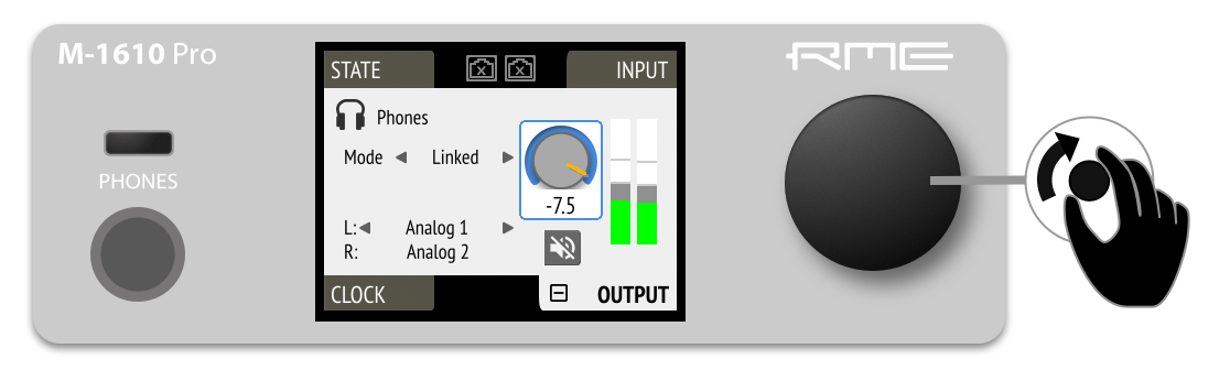
Press the PHONES Button above the headphone output.
-
Rotate the encoder to adjust the gain.
-
Open the phones configuration by pressing the PHONES button above the headphone output.
-
Confirm the current gain by pressing the encoder.
-
Rotate the encoder to navigate to "Mode" and press it.
-
Rotate the encoder and choose "Independent". The current Phones window is now dedicated to the left Phones channel. Press the PHONES button again to open the right output channel.
Follow this procedure to join the two channels as a Stereo channel, reverting to "Linked" as the output mode.
-
Open the corresponding output channel strip.
-
Use the encoder to adjust the gain in the 'PHONES' channel strip.
| Press the Shift key while dragging the knob for finer adjustments. |
| Clicking twice on the encoder knob opens a text field that can be used to input a value using the keyboard. |
-
Press the Button labeled "Stereo". The button turns grey and a second channel strip opens with its own gain control.
Press the "Stereo" button again to create a stereo channel.
| Any previously created gain offset between left and right channel will be ignored when joining the channels to a stereo group. |
Muting the Phones Output
-
Press the PHONES button above the phones output.
-
Confirm the current output gain by pressing the encoder once.
-
Turn the encoder to highlight the MUTE button.
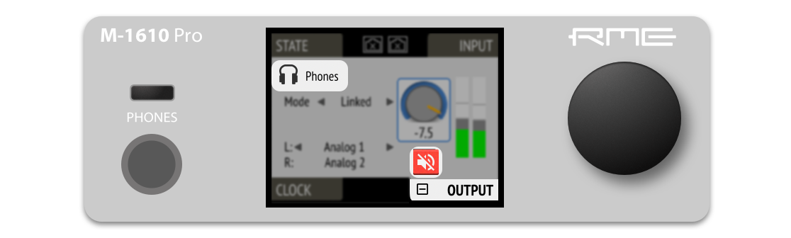
-
Press the mute button. It turns red to symbolize that the phones are muted.

-
Press the mute button in the Phones output channel.
Using Phones Out as a Balanced Line Output
The headphone output can operate as a mono balanced line level output. This may for example be useful when an active talkback speaker with symmetrical input is connected to the 12Mic.
-
Press the PHONES button to access phones output settings.
-
Confirm the current gain by pressing the encoder, then turn the encoder to navigate to "Mode".
-
Push and turn the encoder to activate "balanced", push again to confirm. The channel that was routed to the left phones output will now be applied to both tip and ring of a TRS connector, the phase being inverted on the ring.
-
Open the phones output channel.

-
Press the BAL button to switch the channel to balanced out. The channel that was routed to the left phones output will now be applied to both tip and ring of a TRS connector, the phase being inverted on the ring.