OUTPUT Section

The output section represents the internal routing matrix and state of the outputs. Routing is performed by selecting an output and assigning any input to it. When a routing is active, its input is automatically monitored for lock and sync in the input section. For AVB stream outputs, their states are additionally monitored in the output section.

Example:

In the OUTPUT section, MADI Optical 1-12 is chosen as source for AVB Stream 2.

The 12Mic is clock master, but the incoming MADI signal is not correctly synchronized. This causes a warning in the INPUT section. If MADI Optical is not routed to any output, an invalid or missing signal does not cause a warning.

Use the web remote to find out quickly which outputs are receiving a specific input signal. The web remote provides a thorough representation of all active routing connections at a glance.

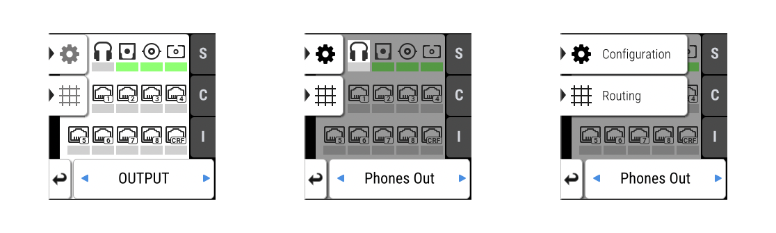
Device Output Section

Within the output section of the device, each output port has individual tabs for configuration and routing. The routing is shown per output channel, it is therefore necessary to browse through the channels to see the current routing.

Access the output section by pressing the encoder once from the main screen, and then rotate it to highlight OUTPUT. Confirm again with an encoder press.
w12 300 1C 1

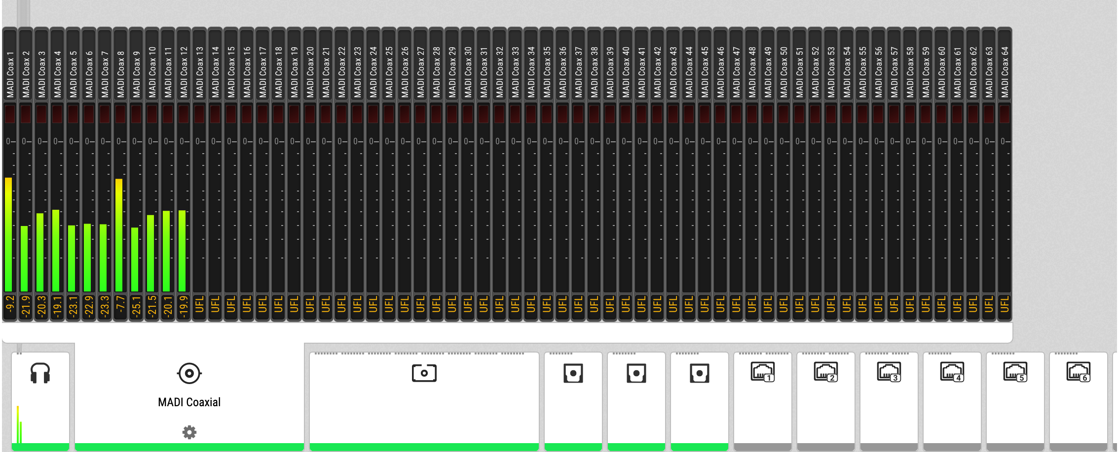
Web Remote Output Section

The web remote integrates the output ports with a visual routing interface. Output ports are shown as icons along the bottom of the screen, with visualized routings that point to the corresponding inputs. Each port can be opened to reveal its output levels, settings, and detailed routing. AVB output ports reveal their current streaming state at a glance.

w12 300 1C 2

Routing Signals to the Outputs

Each output channel of the 12Mic can receive any input signal. If preset 1 has not been modified, it contains a routing of all analog inputs to all digital outputs. However, this can be adjusted and changed easily. The factory default preset does not contain any routing.

A routing immediately activates input monitoring for a corresponding digital input and raises a warning in the input state if the source signal is not available or out of sync.

The following example shows the procedure to route to MADI Coaxial output channels. Other outputs follow the same procedure.

To create a routing to a MADI Coaxial output:
  1. Open the routing tab of the MADI Coaxial output in the OUTPUT section (see device control).

    Coaxial Output
  2. Activate the routing destination and choose an output channel with the encoder (steps 1 and 2).

  3. Activate the routing source and choose an input channel with the encoder (steps 3 and 4).

To remove a routing:
  1. Navigate to the corresponding output channel (1, 2).

  2. Double click on "Increment routing". The routing source will be changed to "not routed".

  3. (optional) Hold "increment routing" while turning the encoder to remove routings to the following output channels.

To route consecutive channels:
  1. Navigate to the first output channel (1, 2) and create a routing as described above.

  2. Hold "increment routing" while turning the encoder clockwise to increment input channel and output channel at the same time.

To create a routing to a MADI output on the web remote:
  1. Enter the Routing mode by pressing the corresponding icon in the title bar.

  2. Click the MADI coaxial or MADI optical output port.

  3. Select individual or consecutive channels by clicking or dragging. The channels are highlighted in blue and an arrow handler is revealed.

  4. If the input ports are closed, drag the handle onto an input port, it opens automatically.

  5. Drag the handle onto the source channel strips to select a range of channels as signal source.