Word Clock
Word clock can be sent and received via 75 Ω coaxial cabling at the corresponding BNC connectors. The cable length should not exceed 100 m (330 ft).

| The input is terminated with 75 Ω internally. To pass on the word clock to other devices, use the word clock output. Do not connect a T-adapter to the word clock input. |
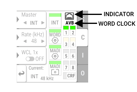
The state of an incoming word clock signal can be accessed in the CLOCK section.
-
A green indicator shows that the signal is currently in sync with the chosen clock master.
-
An orange indicator means that a word clock is received but is not in sync.
-
A red indicator means that word clock is chosen as reference, but a signal is not present or has a different sample rate than device.
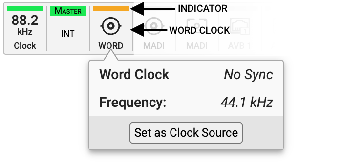
The state of an incoming word clock signal can be observed in the CLOCK section.
-
A green indicator shows that the signal is in sync with the current clock reference.
-
An orange indicator means that a word clock is received but is not in sync.
-
A red indicator means that word clock is chosen as reference, but a signal is not present or has a different sample rate than device.