Analog Inputs
The analog inputs of the 12Mic can be configured at the device or remotely. Gain, AutoSet gain, phase, and phantom power (48V) can be set for individual inputs. In addition, the first four channels support toggling the input to TRS. While switched to TRS, the impedance can be set to High-Z for instrument signals.
| Phantom power is only available at the XLR input, high impedance only at the TRS input. When toggling from TRS to XLR, the current High-Z setting is stored and recalled to its previous state when toggled back. The phantom power setting is not stored and will be switched off when toggling the channel to TRS. |
| To protect the input stage, only switch on phantom power after connecting a compatible condenser microphone or accessory. Remember to switch off phantom power when unplugging a microphone and before saving a preset. |
| The gain, AutoSet and phase settings are not affected when toggling between XLR and TRS inputs. |
Latency and default routing
At single speed sample rates, the converters are configured with short delay 'sharp' IIR filters with extremely low latencies (5 samples) and flat frequency response over the entire audible range. At higher sample rates, a short delay 'slow' filter is used to additionally optimize the impulse response. The latency increases to six samples at quad speed (176.4 kHz, 192 kHz).
A new device has a user-writeable preset 1 with the following "quick start" routing. While the factory default preset (16) does not contain any routings, preset 1 is convenient for plug’n’play operation.
| save preset 1 to any other preset for backup if it appears to be useful. It can be restored into temporary memory by pressing the first button next to the display while powering on. |
-
both MADI coaxial and optional MADI SFP (channel 1-12),
-
AVB stream 1 (AAF, 8 channels)
-
AVB stream 2 (AAF, 8 channels, inputs 9-12)
-
AVB stream 3 (AAF, 12 channels)
-
ADAT port 1 (inputs 1-8) and port 2 (inputs 9-12)
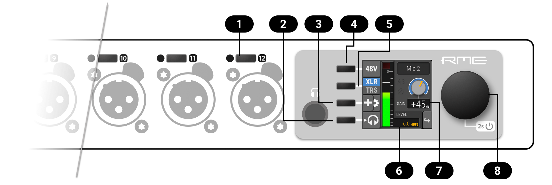
Analog Input User Interfaces
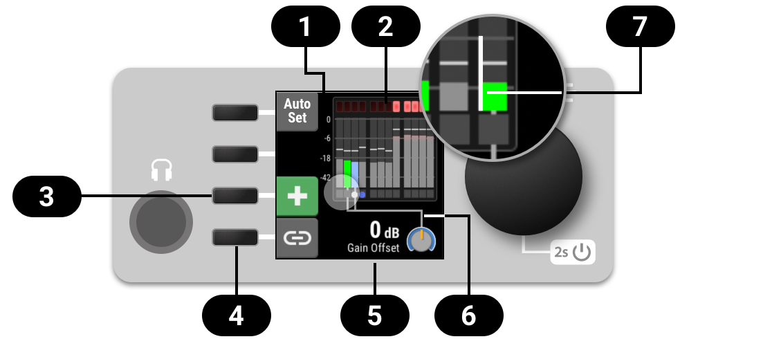
Each analog input channel at the device has its own button. The button activates a settings dialog on the screen.
|
Activate channel controls |
|
Monitor to phones |
|
Gain Groups, Phase and AutoSet |
|
|
|
|
|
Current Input Level |
|
Current Gain |
|
Encoder |


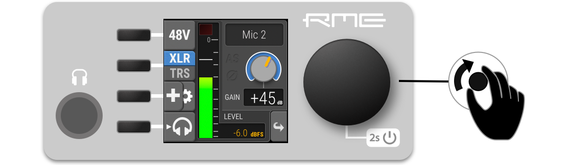
Adjusting the Input Gain
-
Press the button next to the input. The current gain will be shown on the screen.
-
Rotate the encoder to adjust the gain.
-
In the Remote Control Overview, open the analog input port. Each input is represented with a channel strip.
-
Drag the GAIN knob vertically or horizontally.
-
Hold SHIFT to adjust in smaller increments (fine-adjust).
-
Double-click the knob to enter a specific value and confirm with ENTER or ✔️.
-
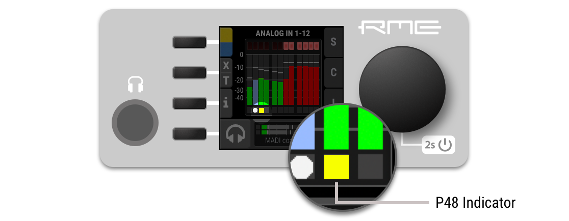
Enabling Phantom Power (P48)
Channels with active phantom power are shown on the standby-screen with a yellow square indicator.
-
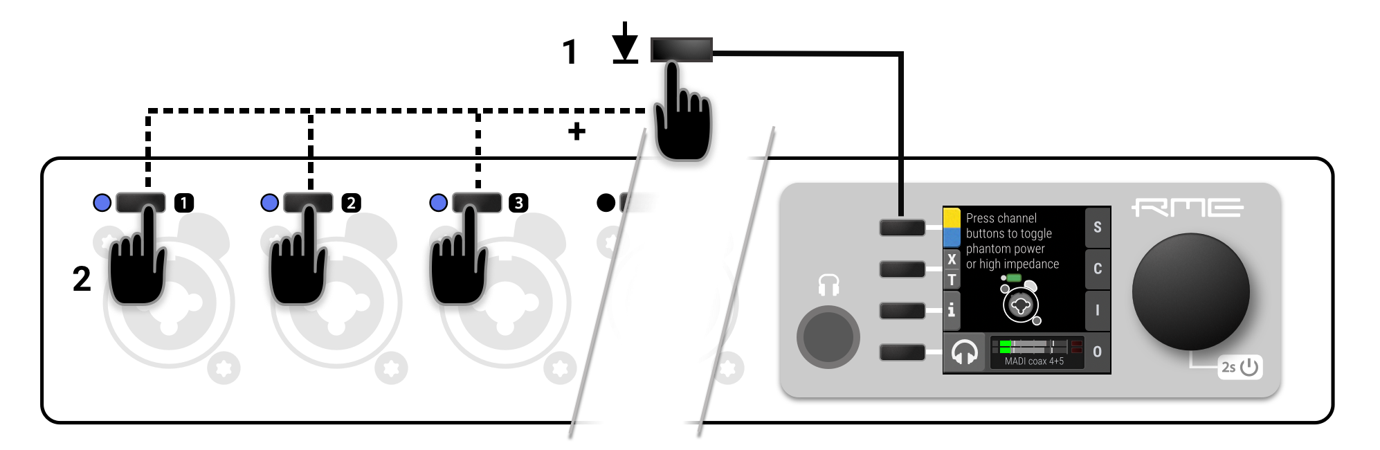
While the standby screen shows the input level meters, press and hold the first button next to the yellow indicator. An instruction is shown on the display and the LEDs next to the input channels change to off (no phantom power) or yellow (phantom power active).
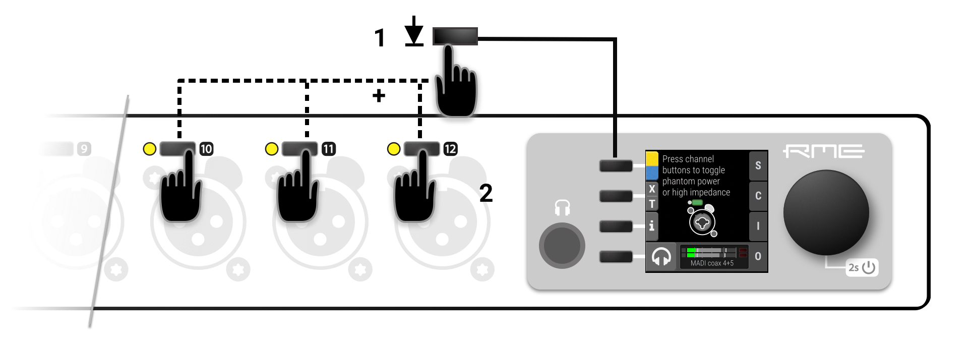
-
While holding down the button, press the channel buttons next to each input where the phantom power should be toggled on or off. A yellow LED at the input represents active phantom power.
-
Use the button next to the analog input to access its settings.
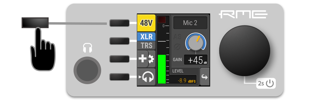
-
Use the P48 button to toggle phantom power.
-
In the Remote Control Overview, open the analog input port. Each input is represented with a channel strip.
-
Press the 48V button in the corresponding channel strip.
| Phantom power settings are not shown when the channel is switched to TRS input. |
Switching Between XLR and TRS Inputs
The input channels 1-4 have "combo-jacks" that support both XLR and TRS connectors. When a plug is inserted, the corresponding input must be selected in the input settings. XLR is the default choice in the factory preset.
| In order to prevent damage due to inrush current, the phantom power setting will be deactivated when toggling to TRS. |
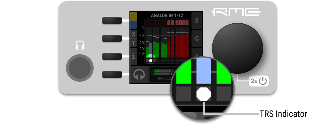
The current input mode is shown on the standby screen:
-
While the standby screen shows the input level meters, press and hold the second button next to the X|T indicator. An instruction is shown on the display and the LEDs next to the input channels change to off (XLR) or white (TRS).
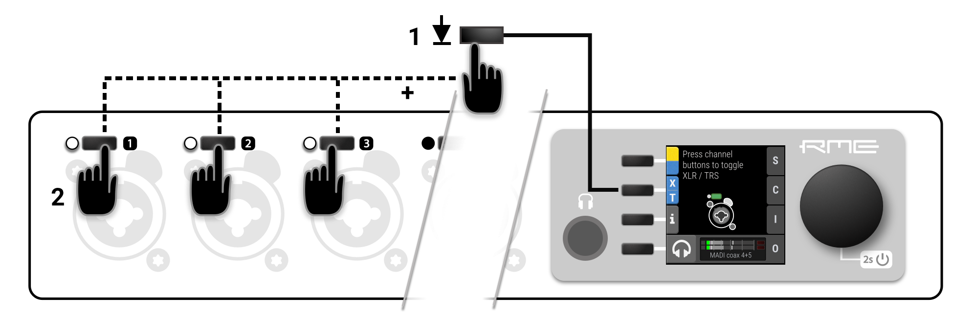
-
While holding down the button, press the channel buttons next to each input where the TRS input should be activated. A white LED at the input represents TRS.
-
Use the button next to the corresponding analog input to access its settings.
-
Use the XLR|TRS button to toggle the change the corresponding input. The active setting will be highlighted in blue.
-
In the Remote Control Overview, open the analog input port. Each input is represented with a channel strip.
-
Press the XLR|TRS button in the corresponding channel strips. The button highlights the currently selected value.
Activating High Impedance (Hi-Z) on TRS Inputs
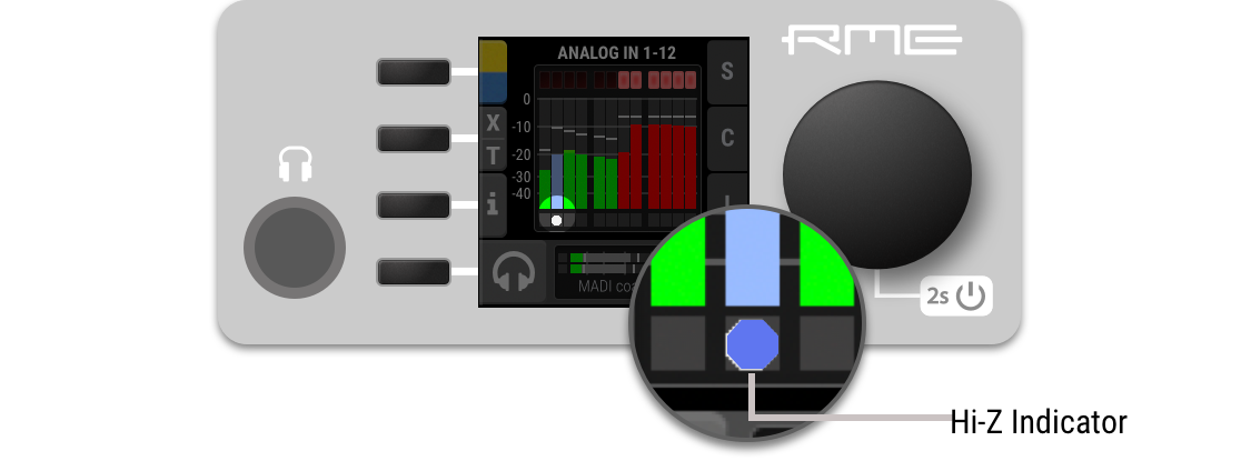
A high input impedance can be activated manually for unbalanced TS connectors on inputs 1-4. The current input mode is shown on the standby screen:
-
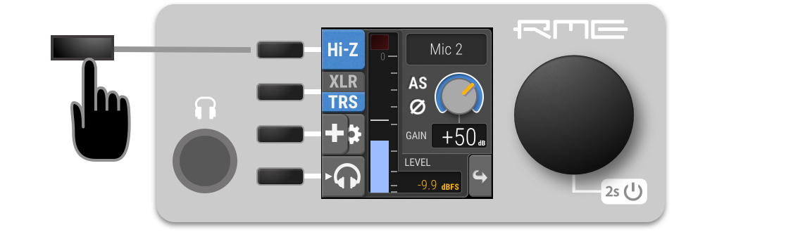
While the standby screen shows the input level meters, press then hold down the first button. An instruction is shown on the display and the LEDs next to the TRS input channels change to white (low impedance) or blue (high impedance).
-
While holding down the button, press the channel buttons next to each TRS input where high impedance should be activated. A blue LED at the input represents high impedance.
-
Use the button next to the corresponding TRS input to access its settings.
-
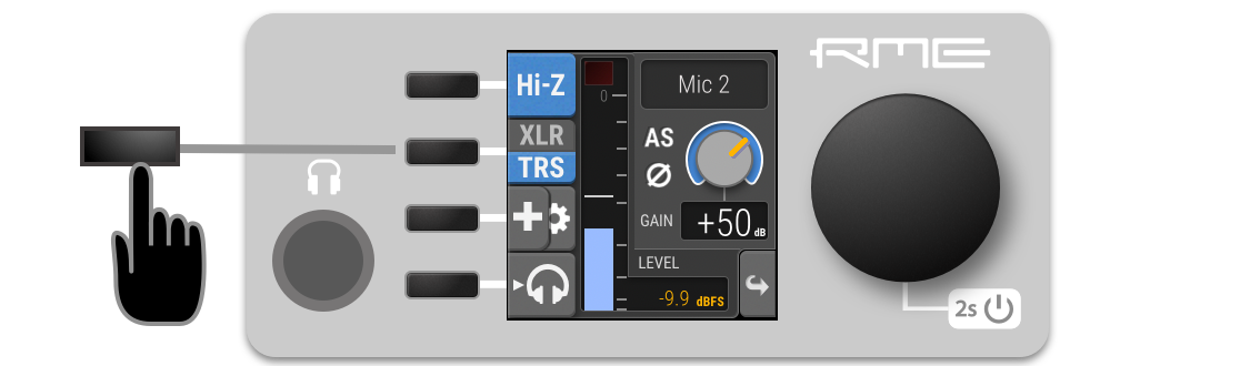
Use the Hi-Z button to toggle high impedance. The active setting will be highlighted in blue.
-
In the Remote Control Overview, open the analog input port. Each input is represented with a channel strip.
-
Ensure that the TRS input is active (state of the XLR|TRS button).
-
Activate high impedance using the Hi-Z button in the relevant channel strips.
| High impedance settings are not shown when the channel is switched to XLR input. |
Inverting the Phase of an Analog Input Signal
The phase of analog input signals can be inverted at the input.
| The setting persists even if the input source is toggled between XLR and TRS. |
-
Use the button next to the corresponding input to access its settings.
-
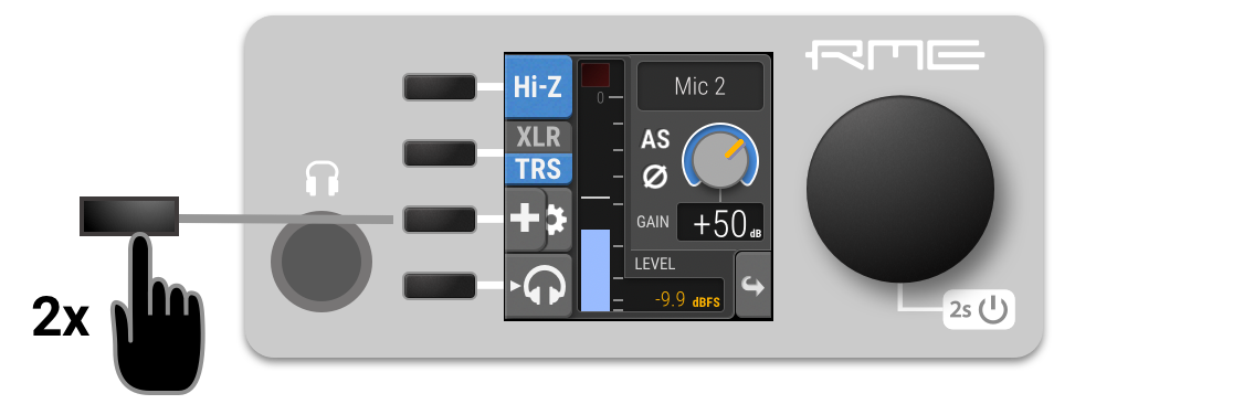
On a combined XLR/TRS input: press the third button twice in quick succession (double press).
-
On an XLR input: press the second button once to access phase and AutoSet settings.
-
Press the second button Ø to invert the phase. It turns yellow when active.
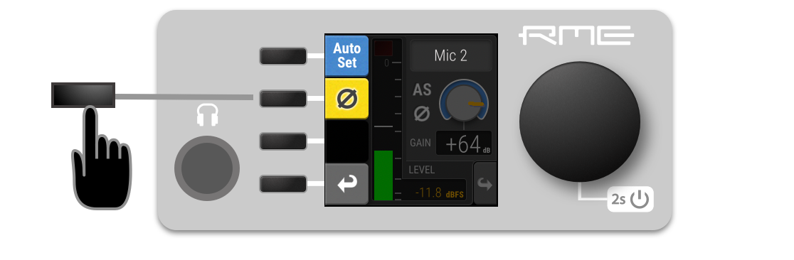
-
Return to the input settings and verify that the Ø sign is shown next to the gain knob.
-
In the Remote Control Overview, open the analog input port. Each input is represented with a channel strip.
-
Invert the phase using the Ø button in the corresponding channel strip.
AutoSet
AutoSet automatically reduces the gain when an input signal exceeds -6 dBFS. It can be set for each input channel individually. When using gain groups, AutoSet can be activated either for the entire group, or only for some channels. Only channels with activated AutoSet will be monitored to maintain the 6 dB headroom, but the resulting gain reduction will affect all channels of the gain group.
| Gain offsets within a gain group are maintained as long as possible. If a participating channel reaches minimum gain, it remains at minimum gain while other channels continue to be reduced. |
The AutoSet feature is very useful during sound checks or rehearsals. Simply set a very high gain and activate AutoSet, then apply the loudest signals to be expected at the corresponding inputs. When signals exceed the -6 dBFS threshold, the gain is quickly attenuated.
| While recording, AutoSet is usually switched off to avoid accidental gain reductions triggered by toggling phantom power, plugging in signals, etc. |
Activating AutoSet
AutoSet can be adjusted in individual channels and gain groups.
| The AutoSet setting persists even if the input source is toggled between XLR and TRS. |
-
Use the button next to the corresponding input to access its settings.

-
On a combined XLR/TRS input: press the third button twice in quick succession (double press).
-
On an XLR input: press the second button once to access phase and AutoSet settings.
-
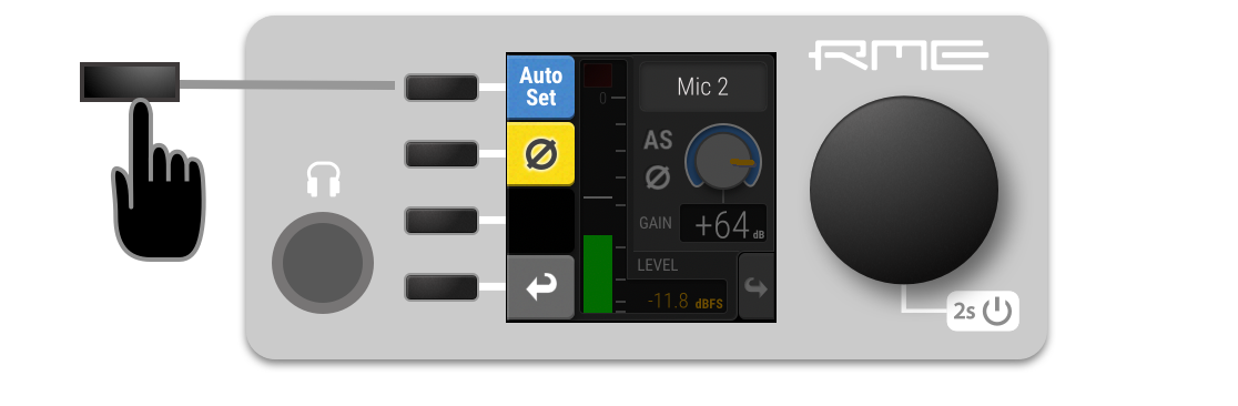
Press the first button AutoSet to activate AutoSet. It turns blue when active.
-
Return to the input settings and verify that the "AS" sign is shown next to the gain knob.
-
Access the gain group or create a new one temporarily.
-
Press the first button AutoSet to activate AutoSet for all participating channels. Individual channels can be excluded from AutoSet threshold monitoring, in which case the AutoSet is shown half blue, half grey.
-
In the Remote Control Overview, open the analog input port. Each input is represented with a channel strip.
-
Use the AutoSet button in the corresponding channel strip.
-
Open a gain group in the Remote Control Overview.
-
Use the AutoSet button in the group panel appearing below the input channel strips. Individual channels can be excluded from AutoSet threshold monitoring, in which case the AutoSet is shown half blue, half grey.
Gain Groups
The gain level of two or more channels can be linked temporarily or permanently. When part of a group, gain is increased or decreased as an offset (in dB) to the previously set individual gain levels. The offset is not stored itself - the adjustment is immediately applied to all member channels.
The group gain offset is not limited by the minimum/maximum gain of the participating channels. As a consequence, gain differences between channels will be reduced when a positive (negative) offset is applied while one of the channels has already reached its highest (lowest) gain setting.
| In order to create an equal gain for all channels in a group, first set the offset of the group to its lowest (negative) value. Then, increase the offset to the preferred gain. |
|
Group Overview |
|
Level meters |
|
Add channels to group |
|
Save group |
|
Current offset |
|
Linked gains |
|
Gain indicator |
| It is possible to adjust the gain of individual channels even when they are part of a gain group. |
Creation and Use of a Gain Group
To create a group that controls the gain of two or more channels at once, proceed with the following steps:
| the group can include TRS inputs that have a different gain range. Applied group gain offsets will be limited by gain range of individual channels. |
-
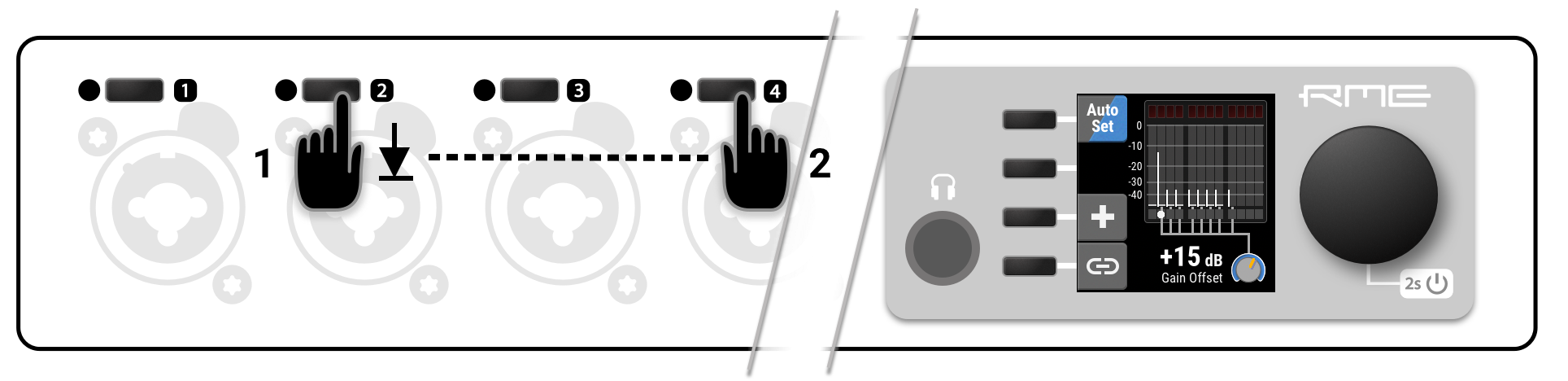
Press and hold the first button at the first input. The channel is selected as the first channel in a group.
-
While holding down the first button, press a second button at another input. All inputs in-between will be added to the group. Release the buttons and adjust gain as required.
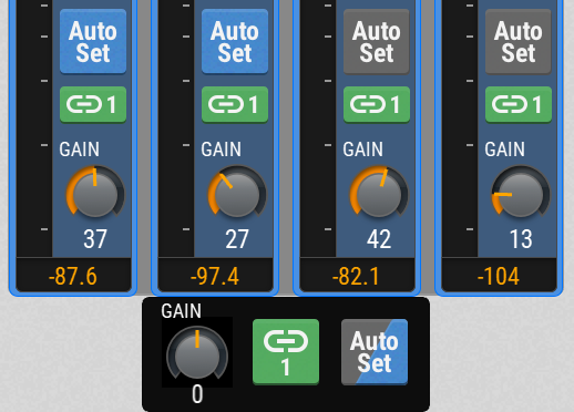
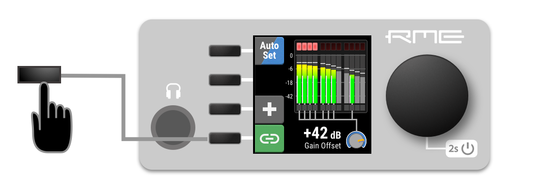
Channels that participate in the current group are shown with full color level meters and connecting lines to the encoder icon (refer picture above). Channels that do not participate in the group have grey level meters and are not connected. -
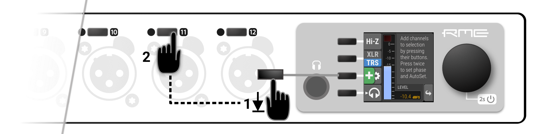
Hold down the third button + and press input buttons to add or remove individual channels from the group.
-
Press and hold the third button +. The button turns green and an instruction is shown.
-
Press a second button at another input. The new gain group is displayed and allows adding further channels.
-
In the Remote Control Overview, open the analog input port. Each input is represented with a channel strip. Note that each channel strip becomes highlighted when the cursor hovers over it.
-
Click or tap the first channel strip (avoiding the control buttons and encoder), and then swipe sideways to select a range of channels. The selected channels get highlighted in blue.
-
Click or tap on individual strips to add or remove them from the selection.
-
Use the additional gain knob floating below the selected channels to adjust the gain for all channels.
Saving, Using and Deleting Gain Groups
A temporary gain group can be saved.
| Groups will be saved in presets and appear on both the device and its web interface. The gain of each channel remains fully independent. |
-
Create a temporary gain group. The selected channels will be shown on the screen, connected by a line attached to the bottom of their level meter.
-
Press the fourth button next to the display. The "link" indicator turns green, indicating a saved group.
| Groups will be saved in presets and appear always on both the device and its web interface. The gain of individual channels remains fully independent. |
-
Press the input button of a participating channel. Instead of the individual channel settings, the group offset dialog will be shown. To continue to individual channel settings, press the input button one more time.
-
Access a previously saved gain group.
-
Press and hold the + button and deselect any participating group channels.
-
Create a temporary gain group. The selected channels will be highlighted in blue, with an additional floating gain control below.
-
Press the link button below the group. The "link" indicator turns green, indicating a saved group.
-
Each channel strip that participates in a gain group has an additional Link button with the number of the corresponding group. This button is used to select the gain group.
-
Access a gain group.
-
Press the Link button with the current group number next to the group gain knob. The group is removed.
Monitor Analog Inputs at Phones Output
The phones output at the front of the 12Mic can receive any input signal. Permanent routings are configured in the Phones Output settings (see Routing Signals to the Outputs and Analog Outputs). Additionally, the analog input screens on the device provide a quick and convenient method to temporarily monitor analog input signals at the phones output.
| when changing the routing, always ensure that the headphone volume is turned down to avoid damage to headphones and hearing. |
-
Ensure that the output volume is adequate (see Analog Outputs)
-
Press the button next to the corresponding channel to open the channel settings.
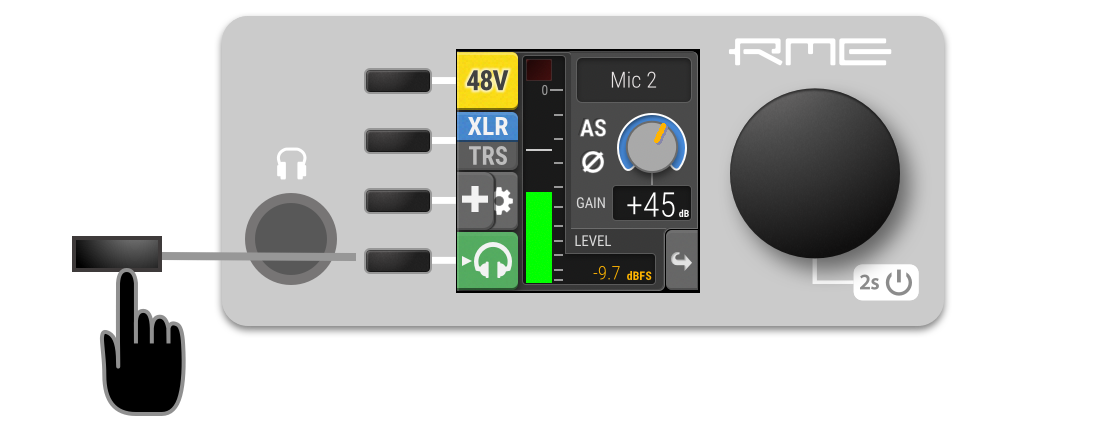
-
Use the fourth button to send this channel to the Phones Output (left and right) The button turns green, indicating that temporary routing has been established. The green button is also shown on the main screen and in the phones output settings.
-
Deactivate the routing by either pressing its button in the corresponding input channel, or
-
by opening the phones output and deactivating the mode there. If there was a previous routing, it will be re-established immediately.
This function is only available on the device.